Ejector pins are the most widely used ejection method in injection molding. They are easy to machine — even when hardened steel is required — and can be placed almost anywhere on the part. Pin holes are also easy to machine with good accuracy, and the system offers low sliding resistance, minimal sticking, excellent interchangeability, and straightforward maintenance.
The most common ejector components include round pins, stepped pins, blade pins, and ejector sleeves.
However, ejector pins apply force over a small area, concentrating stress locally. For cup‑shaped or box‑shaped parts with shallow draft angles and high demolding forces, pin ejection may cause indentation or even piercing. In such cases, pins are often not the best choice.
Placement Guidelines
Place pins around the perimeter first, then under ribs. Position them where the part is strongest — under ribs, bosses, or side walls — to minimize stress whitening.
On large flat surfaces, use ejector sleeves instead of small pins. Sleeve wall thickness: at least 1 mm; inner and outer diameters should be integers.
Avoid placing pins under slides. If unavoidable, add an early return mechanism.
Use the same pin diameter wherever possible to simplify machining and spare parts inventory.
Selection Considerations
Size and strength – Use the largest practical pin diameter to spread ejection force. For pins ≤ 2.5 mm, use stepped pins with a larger shank. For sleeves with wall thickness < 1 mm or wall‑to‑diameter ratio ≤ 0.1, specify stepped sleeves with the longest practical shank.
Engagement length – Effective guide length should be 2.5–3× the pin diameter, minimum 8 mm.
Pin height – Pin face should be 0.03–0.05 mm above the core surface. For flatness‑sensitive parts, add a shallow counter‑bore.
Avoid weak areas – Do not place pins at insert joints or parting lines. These areas are prone to flash and mismatch.
Tall ribs – For ribs higher than 10 mm, use blade pins (flat ejectors) to prevent distortion.
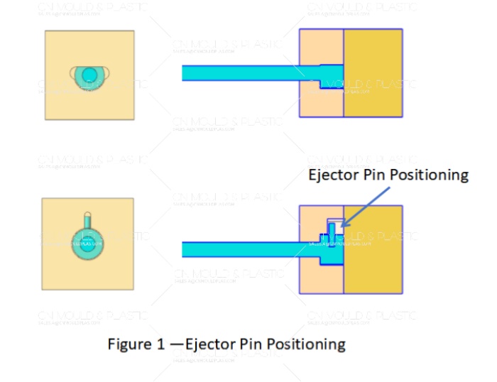
Angled surfaces – If the pin face is on an angle, use an anti‑rotation feature to prevent spinning (see Figure 1).

 English
  français
  Deutsch
  Español
  italiano
  русский
  português
  العربية
  dansk
dansk  Suomi
Suomi  Svenska
  norsk
norsk