Plastic gears are increasingly used in electromechanical devices, consumer products, and transmission systems where high precision and strength are not the primary requirements. Their advantages include light weight, low elastic modulus, and reduced noise transmission compared to steel or cast iron gears—even at similar manufacturing precision levels.
Common plastics used for gear manufacturing include:
Polyamide (PA)
Polyoxymethylene (POM)
Polycarbonate (PC)
Polysulfone (PSU)
Design Considerations for Injection-Molded Plastic Gears
To ensure successful injection molding and reliable performance, plastic gears must be designed with specific dimensional relationships:
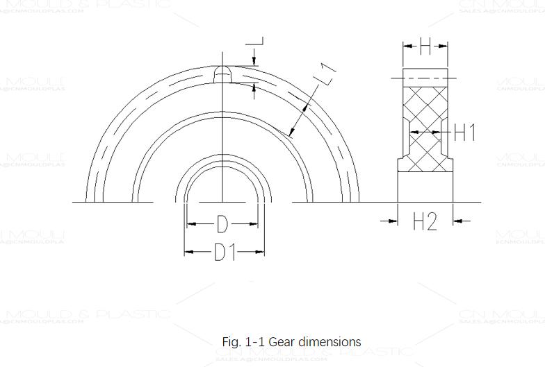
Rim width should be at least 1 times the full tooth height.
Web thickness (H₁) must be less than or equal to rim thickness (H₁).
Hub thickness (H₂) should be greater than or equal to rim thickness (H₁) and roughly equivalent to the shaft hole diameter (D).
Minimum hub outer diameter (D₁) is recommended to be 1.5–3 times the shaft hole diameter (D).
Refer to Figure 1-1 for detailed dimensional guidelines.
Avoiding Stress Concentrations
Since gears undergo cyclic loading, sudden changes in cross-section should be avoided. All transitions between surfaces should incorporate generous fillets to minimize stress concentrations and molding-induced stresses.
Assembly and Torque Transmission
To prevent assembly stress:
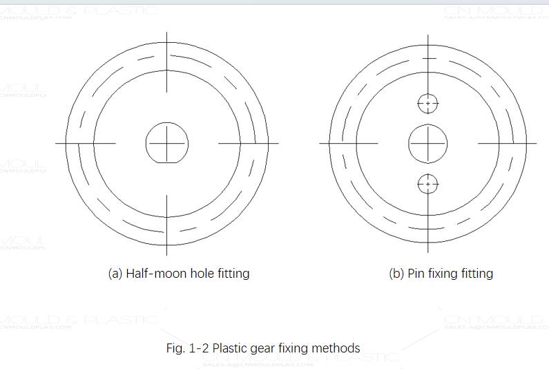
Handling Thin Gears and Warpage
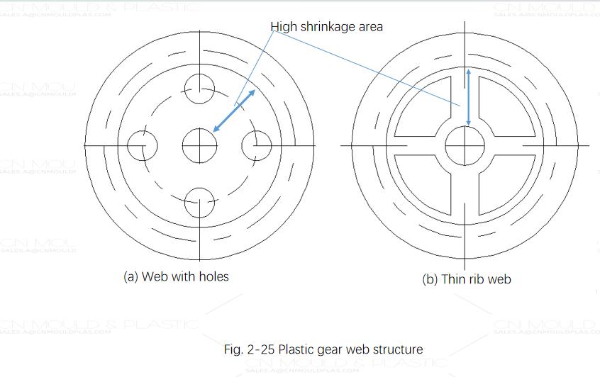
For thin gears, uneven thickness can cause tooth distortion. Rimless and hubless gear designs can help improve uniformity. However, if large holes are present in the web—as in Figure 1-3(a)—minimal inward shrinkage during molding may still lead to tooth misalignment.
A better approach is to use thin ribs between the hub and rim, as shown in Figure 1-3(b), which allows the rim to shrink inward uniformly and maintains gear accuracy.
Material Compatibility in Meshing
Due to the relatively high shrinkage rates of plastics, it is generally advisable to pair gears made from the same material to ensure consistent meshing performance and avoid operational issues.

 English
  français
  Deutsch
  Español
  italiano
  русский
  português
  العربية
  dansk
dansk  Suomi
Suomi  Svenska
  norsk
norsk