Runner design is a critical aspect of mold design. The cross‑sectional shape of the runner directly affects melt flow, pressure loss, and mold manufacturing cost. There are four commonly used runner profiles, as shown in Figure 1-1, each with its own advantages, limitations, and preferred applications.
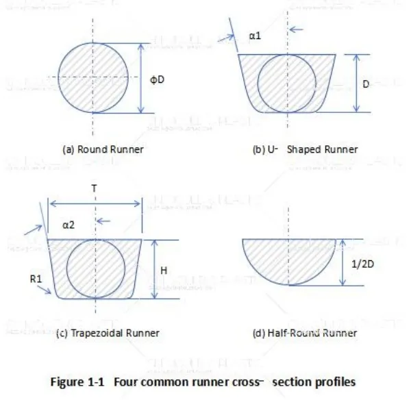
Round Runner
The round runner is the most widely used profile. Its circular cross‑section offers the lowest flow resistance and minimal pressure loss, making it ideal for delivering melt efficiently to the cavity.
However, this design requires machining on both mold halves using a ball‑end cutter, which increases machining time and cost. Despite this drawback, its superior flow characteristics make it the preferred choice for most applications where flow performance is the primary concern.
U‑Shaped Runner
The U‑shaped runner is machined on a single mold plate — either on the core side or the cavity side, depending on the mold structure. This makes it easier and less expensive to machine than a round runner.
The side wall angle (α₁) should be approximately 10°, with a recommended range of 5° to 15°. A tapered ball‑end cutter is typically used for machining. The U‑shaped profile offers a good balance between flow efficiency and ease of manufacturing, with low demolding resistance.
Trapezoidal Runner
The trapezoidal runner is another commonly used profile. Like the U‑shaped runner, it is machined on a single plate, making it more economical to produce. It is even easier to machine than both the round and U‑shaped profiles.
The side wall angle (α₂) should also be approximately 10° (5°–15° range). A corner radius (R₁) of 1.0–1.5 mm is recommended at the base to reduce stress concentration and improve flow. This profile is particularly common in three‑plate molds (pin‑point gate systems), where its manufacturability and low demolding resistance are highly valued.
Half‑Round Runner
The half‑round runner is rarely used for the main sprue or primary runners, but it is frequently employed for final branch runners in small products.
For small parts, the flow capacity and pressure compensation provided by a half‑round runner are often sufficient — there is no need to machine a full round runner. The machining volume of a half‑round runner is only half that of a round runner, making it significantly more economical. It is machined on a single plate using a ball‑end cutter, and the plate choice (core or cavity) depends on the mold structure.
Runner Sizing Guidelines
Standard runner diameters are available in increments: 2.0, 2.5, 3.0, 3.5, 4.0, 4.5, 5.0, 6.0, and 8.0 mm.
Sprue (main runner):
Branch runners (by level):

 English
  français
  Deutsch
  Español
  italiano
  русский
  português
  العربية
  dansk
dansk  Suomi
Suomi  Svenska
  norsk
norsk