Introduction
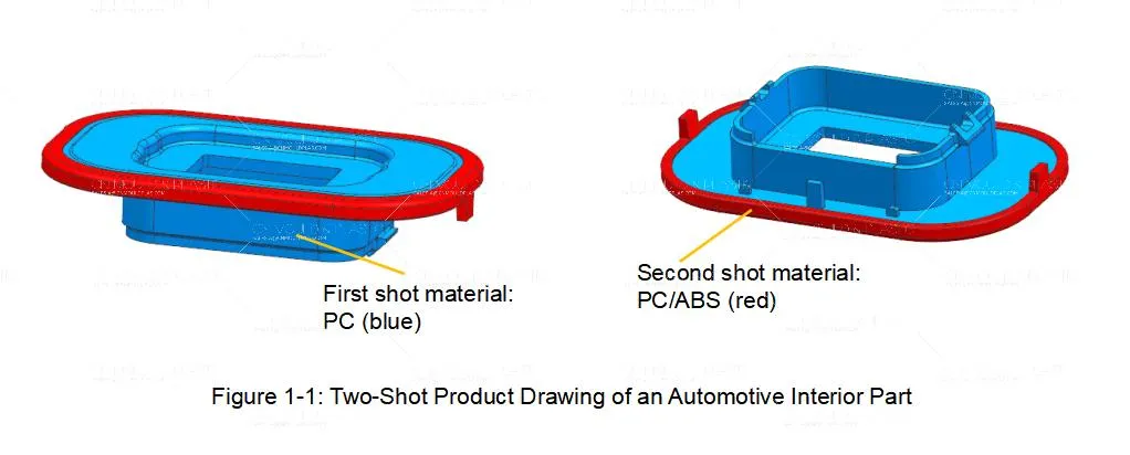
This is a mold design for a two-shot automotive interior part (see Figure 1-1). The component measures 92 × 210 × 50 mm. The blue section is molded from the first-shot material, PC, while the red section is molded from the second-shot material, PC/ABS. Both are rigid plastics. The structure is not complex, and the size is medium. It is a basic two-shot product, and the mold is required to produce 1+1 cavities per cycle.
Parting Line Design
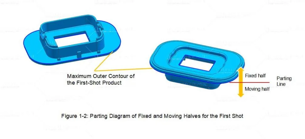
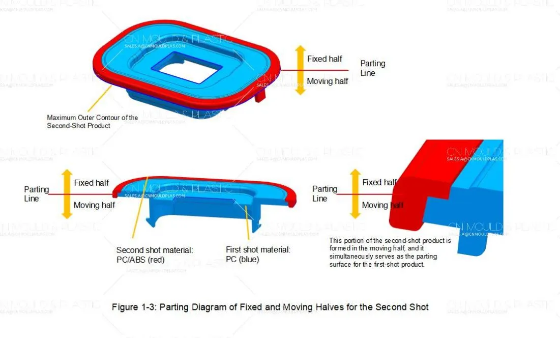
In mold design, the first step is always the parting surface. For this product, the first-shot parting line is easy to define — we take its maximum outer contour as the parting line between the fixed and moving halves (see Figure 1-2). The second-shot plastic wraps around the first-shot product, so its parting line also follows the maximum outer contour (see Figure 1-3). Here's the key point: part of the second-shot product is formed in the moving half. That same portion also serves as the parting surface for the first-shot product.
At this stage, the product meets the basic principle of two-shot mold design — the fixed half is different, and the moving half stays the same. The moving-side cavity and parting surface for both shots must be exactly identical. So the second-shot cavity geometry has to act as the shut-off surface for the first shot (see Figure 1-4 and Figure 1-5).
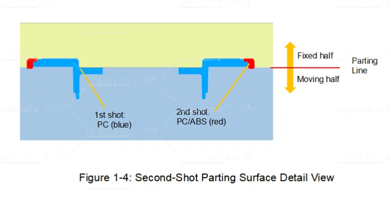
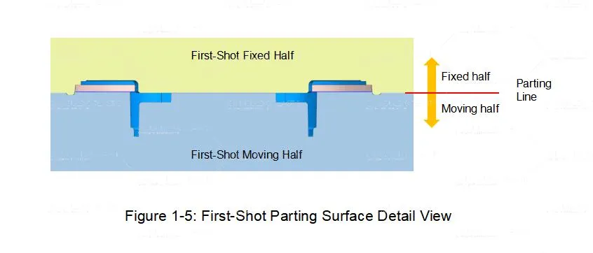
So what is shut-off? It means that at the parting surface, the first-shot product must leave a space that matches the second-shot cavity exactly. This way, when the second shot is injected, the melt won't overflow into places it shouldn't go. If the shut-off is not done well, you'll get flash on the second shot, or the first-shot product will be crushed during mold closing. That's why the key design point comes down to one thing: the shut-off treatment on the first-shot parting surface.
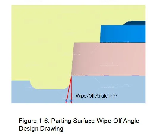
The core of shut-off treatment is controlling the wipe-off angle on the inner surface of the second-shot cavity. This angle must be greater than or equal to 7° (see Figure 1-6). If the angle is too small, the core is easily scratched, and over long-term production, it will also lead to flash on the product. By keeping the angle sufficient, we both protect the mold and reduce the difficulty of mold fitting.
Gate Design
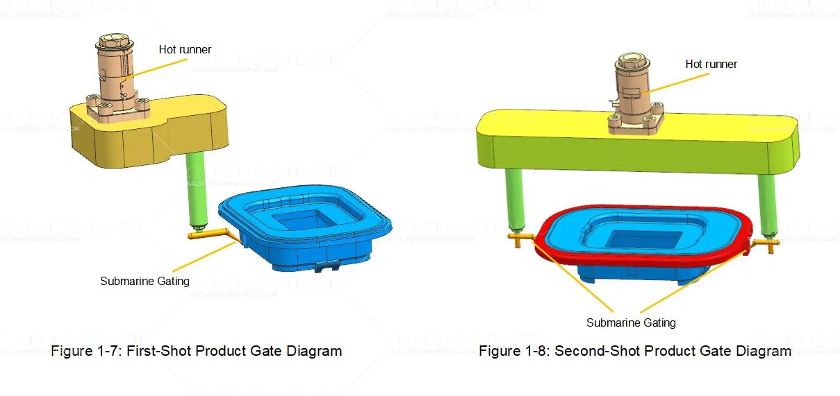
For gating, both shots use a hot runner feeding into submarine gates (see Figure 1-7 and Figure 1-8). The first shot, PC, uses one submarine gate. The second shot, PC/ABS, uses two submarine gates. The product has high appearance requirements, and submarine gates have little impact on the surface, making them suitable for this situation.
Ejection System
The moving half has four undercuts, which are formed and demolded by angled lifters. After the first shot is injected, the moving half rotates 180° for the second-shot injection. After the second shot is complete, the angled lifters and ejector pins act together to eject the product. The angled lifters complete the lateral core-pulling of the undercuts while ejecting — they are both forming components and ejecting components.
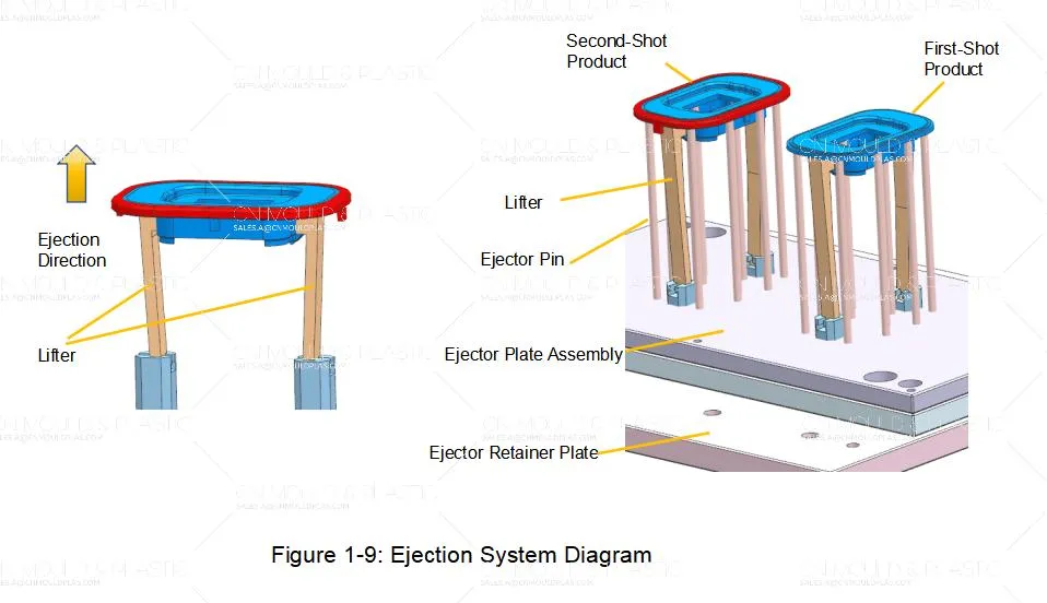
One thing to note here: after the first-shot product is injected, it is not ejected. Its cold runner remains on the moving core. Therefore, when designing the fixed-half cavity for the second-shot product, a clearance hole must be designed for the first-shot cold runner. Otherwise, during the second mold closing, the mold will directly crush the cold runner, causing damage.

 English
  français
  Deutsch
  Español
  italiano
  русский
  português
  العربية
  dansk
dansk  Suomi
Suomi  Svenska
  norsk
norsk