Locating pins (also called dowel pins) play a critical role in mold assembly. They ensure accurate alignment between mold plates and components, maintain assembly precision, and resist lateral shear forces during mold operation.
Function of Locating Pins
In mold construction, locating pins are used to align:
Clamping plate and cavity plate
Ejector plate and support pillars
Guide rail plates and slide holders
Typically, two or four pins are used per connection to achieve precise alignment and withstand shear forces.
Selection Guidelines
Pin type – Choose cylindrical dowel pins for through‑holes, and tapered pins for blind holes. Tapered pins are easier to remove during maintenance.
Pin placement – Position the two locating pins as far apart as possible, near the outer corners of the component, and avoid symmetric placement.
Pin diameter – Select the pin diameter based on the expected shear force and the size of the mold plates.
Pin depth – The engagement length in the hole should generally be at least twice the pin diameter — deeper engagement does not improve alignment and may complicate assembly.
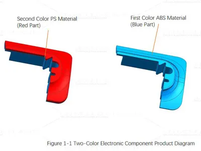
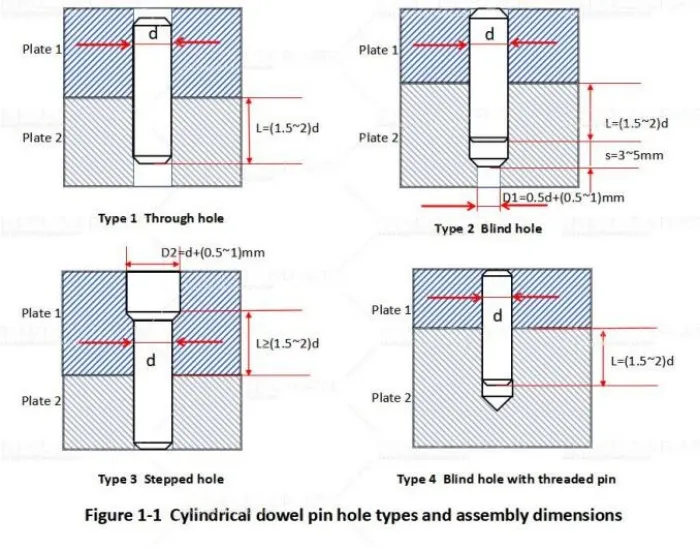
Hole Design Guidelines(see Figure 1-1)
When both plates are 50 mm or thinner, a straight through‑hole is used. The pin should have full engagement in the first plate, and the engagement length in the second plate should be 1.5 to 2 times the pin diameter L = (1.5~2)d.
When the second plate exceeds 50 mm in thickness, a blind locating hole is used on that plate. The pilot hole diameter (D₁) should be 0.5d + (0.5~1) mm. The recommended engagement length (L) is 0.5 to 2 times the pin diameter, and a clearance depth (s) of 3~5 mm should be reserved at the bottom of the hole for chip accumulation and pin insertion.
When the first plate exceeds 50 mm in thickness, a stepped clearance hole is used. The clearance diameter (D₂) should be d + (0.5~1) mm, with a minimum engagement length (L) of 0.5 to 1 times the pin diameter.
When the second plate is thick or a through‑hole is not permitted on the bottom surface, use a blind hole with a threaded dowel pin. The engagement length (L) should be 0.5 to 2 times the pin diameter.

 English
  français
  Deutsch
  Español
  italiano
  русский
  português
  العربية
  dansk
dansk  Suomi
Suomi  Svenska
  norsk
norsk