Hot runner systems offer significant advantages — no runner waste, shorter cycle times, and consistent part quality. But they also demand careful design. A poorly designed hot runner can cause leakage, blockage, thermal degradation, and costly production delays.
Here are the key design considerations and structural requirements for building a reliable hot runner mold.
Design Considerations
1. Smooth flow path – All runner junctions and turns must have smooth radius transitions. Sharp corners or dead zones trap material, causing degradation and discoloration. Every flow path should allow the melt to move freely without stagnation.
2. Thermal insulation – Hot runner components must be well insulated from the surrounding cold mold plates. Air gaps of 10–15 mm are typically used to prevent direct contact with the cavity plates. Direct contact causes heat loss through conduction and radiation, leading to temperature instability.
3. Heating power and warm-up time – The heating power of the manifold must be calculated to ensure it reaches operating temperature within a reasonable time — typically 30 to 60 minutes (30 minutes is preferred). The system should be designed for consistent, uniform heating.
4. Thermal expansion compensation – During operation, the manifold runs at 200–300°C while the cavity plates are typically 60–80°C. This temperature difference causes thermal expansion, which can misalign the manifold nozzle with the sprue bushing. This offset must be calculated in advance and compensated for in the design.
5. Preventing nozzle drool, clogging, and degradation – These are common issues, especially with open nozzles. Poor assembly tolerances between the nozzle and the cavity plate can cause leakage or flow restriction. Material properties — especially for heat-sensitive resins — must also be considered.
6. Gate location and sizing via CAE analysis – Gate positions and sizes must be determined through CAE flow analysis to ensure balanced cavity filling and minimal pressure loss before any metal is cut.
Structural Design Requirements
Heating method and heater fit – Manifold heating can be internal or external, but must be uniform. The fit between the heating elements and the manifold bores should follow an H7/g6 clearance. If the clearance is too large, the heaters will overheat and fail prematurely. If it is too small, assembly becomes difficult.
Manifold geometry and runner sizing – Manifold shapes can be straight, H‑shaped, X‑shaped, or Y‑shaped, depending on the part layout. The manifold should be as light as possible while maintaining sufficient strength. Runner diameters typically range from 6 to 14 mm, depending on the part size and material type.
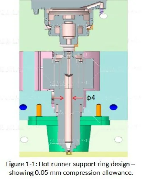
Support rings (pressure pads) – Support rings are placed above each nozzle or below the injection nozzle to secure the manifold. They should be double‑recessed to reduce contact area. Nozzle tips are typically made of beryllium copper for thermal conductivity; support rings are usually stainless steel for thermal insulation. A compression allowance of 0.03–0.05 mm should be left — the assembled height of the support ring and manifold/nozzle should be 0.025–0.05 mm higher than the available space in the fixed mold plate, as shown in Figure 1-1.
Positioning and thermal expansion – The manifold is positioned using locating pins. Long slots milled along the centerline at both ends allow for thermal expansion while maintaining alignment. A small clearance (0.2–0.5 mm) between the nozzle and the cavity plate acts as a thermal barrier. Thermal expansion must be calculated and noted on the mold drawing — if the nozzle expands axially when heated, the expansion amount should be measured and compensated so that the nozzle aligns flush with the cavity plate at operating temperature.
Sizing guidelines – For runner diameter: when the shot size is small and the runner length is under 200 mm, the runner diameter is primarily determined by shot volume. For longer runners, a larger diameter is recommended to minimize pressure loss and heat loss. For nozzle gate diameter: the free flow diameter should match the nozzle channel diameter. Refer to manufacturer sizing charts for specific recommendations based on material and part weight.

 English
  français
  Deutsch
  Español
  italiano
  русский
  português
  العربية
  dansk
dansk  Suomi
Suomi  Svenska
  norsk
norsk