The success or failure of a mold is often decided the moment the gate location is set.
We've seen too many cases where the mold is machined to high precision, the injection machine is top-tier, but the part is still unstable — visible weld lines, local sink marks, recurring flash. The technician adjusts temperature, pressure, speed, and nothing works.
The problem isn't the process parameters. It's the gate location.
What Happens When the Gate Location Is Wrong?
First, weld lines and trapped gas are unavoidable.
The gate location determines how the melt flows through the cavity. If the flow path is unreasonable, weld lines form where two melt fronts meet, and gas gets trapped in dead corners. These problems cannot be solved by adjusting temperature, pressure, or speed — because the root cause was set at the mold design stage.
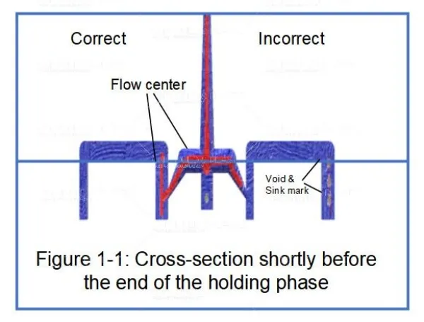
Second, thin-wall gating hurts the thick sections.
If the gate is placed in a thin-wall area, that area cools and solidifies first. By the time the thick section still needs packing, the flow path is already frozen. The result: sink marks and voids in the thick sections, as shown in Figure 1-1. This type of problem may not show up during trial molding — it appears after mass production has been running for a while.
Third, long flow distance makes flash impossible to control.
If there are too few gates or the gate is placed too far away, the melt has to travel a long distance to fill the cavity. This requires higher injection pressure — and when pressure goes up, insufficient clamping force means flash. Worse, the processing window becomes extremely narrow. Any slight fluctuation produces defects.
Gate Design: A Few Principles Worth Remembering
Place the gate in the thickest wall section whenever possible, so thick areas fill first and pack properly
Keep the gate away from high-stress areas to prevent cracking during use
For long parts or glass-fiber reinforced materials, use longitudinal gating rather than transverse or center gating
In multi-cavity molds, arrange gates symmetrically relative to the sprue to ensure balanced filling
For gears, discs, and similar parts, use center gating or multi-point pin-point gates to ensure roundness
For parts with living hinges, keep the weld line away from the hinge — never allow flow interruption near the hinge
For cup-shaped parts, gate near the bottom to prevent trapped air
For tubular parts, fill the annular cross-section first, then the length, to avoid asymmetric flow fronts
These principles look simple, but in real projects, part geometry, mold structure, and cosmetic requirements often conflict. Trade-offs are always needed.
A Real Case
A customer had a glass-fiber reinforced PA66 part. During trial molding, the weld line location had insufficient strength — the part cracked repeatedly during assembly.
After analysis, we found that the original gate location caused two melt fronts to meet at the highest-stress area, and the fiber orientation was unfavorable. After adjusting the gate location, the weld line moved to a non-critical area, and the flow front profile was optimized. The part passed the customer's strength test.
Gate location is not a "close enough" parameter. It directly affects part strength, appearance, dimensional stability, and production yield.
If you are developing a new mold, or if your existing mold has persistent defects that are difficult to solve, contact us. We can evaluate the gate design during the DFM stage and help you avoid these pitfalls.

 English
  français
  Deutsch
  Español
  italiano
  русский
  português
  العربية
  dansk
dansk  Suomi
Suomi  Svenska
  norsk
norsk