Design of Exhaust System
The exhaust system plays a crucial role in ensuring the quality of molded products. The exhaust methods include the following:
1. Utilizing exhaust grooves: These are typically placed at the last areas of the cavity to be filled. The depth of the exhaust grooves varies by plastic type and is basically determined by the maximum allowable gap that prevents plastic flash.
2. Using the fitting clearances of cores, inserts, ejector pins, etc., or dedicated exhaust plugs for ventilation.
3. Designing air intake pins to prevent vacuum deformation of the product during ejection.
4. Designing anti-vacuum adsorption components to prevent the product from sticking to the mold due to vacuum.
Design of Cooling System
Designing the cooling system is a meticulous task that requires considering both cooling efficiency/uniformity and the impact on the overall mold structure. It includes:
1. Arrangement and specific forms of the cooling system.
2. Determination of specific locations and dimensions of the cooling system.
3. Cooling of critical areas such as moving mold cores or inserts.
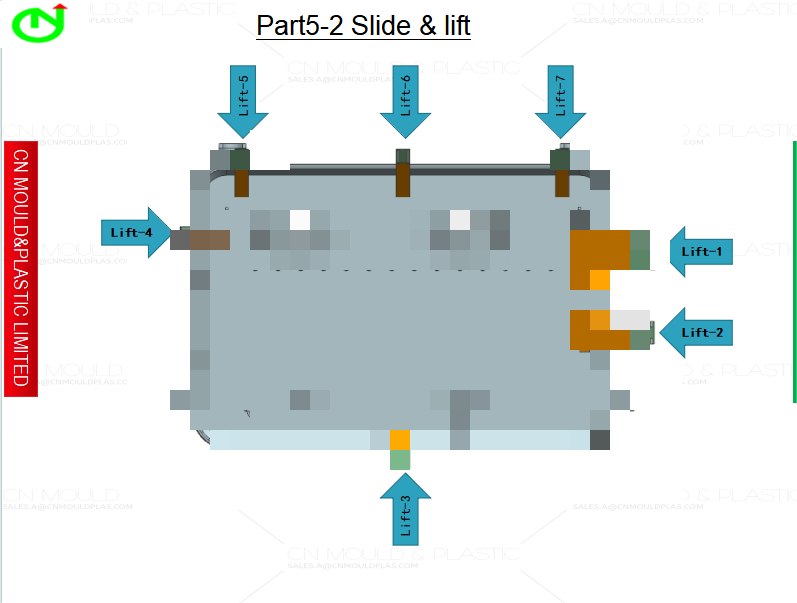
4. Cooling of side slides and side cores.
5. Design of cooling components and selection of standard cooling elements.
6. Design of sealing structures.
Design of Ejection System
Ejection methods can be categorized into three main types: mechanical, hydraulic, and pneumatic.
• Mechanical ejection includes ejector pins, ejector sleeves, ejector plates, ejector blocks, and composite ejection.
The ejection process is the final step in injection molding and directly impacts product quality. Therefore, the following principles should be observed during design:
1. Avoid deformation: Thrust points should be close to cores or areas difficult to demold (e.g., using ejector sleeves for long, hollow cylinders). Arrange thrust points evenly.
2. Target rigid areas: Apply force on areas with high rigidity, such as ribs, flanges, or wall edges of shell-shaped products.
3. Avoid thin surfaces: Prevent thrust points on thin planes to avoid cracking or perforation. Use ejector plates for shell or cylindrical products.
4. Hide ejection marks: Place ejection devices on non-visible or non-decorative surfaces, especially for transparent products.
5. Ensure even force distribution: Use composite ejection or special systems (e.g., combined pins/plates, air intake pins) to prevent vacuum deformation and ensure uniform force. Install air intake valves if necessary.
Design of Guide Devices
For standard mold bases, guide devices are predefined. Designers usually only need to select according to the mold base specifications. However, precision guide devices must be specially designed for high-precision products.
General guiding includes:
• Between moving and fixed molds.
• For ejector plates and ejector pin retaining plates.
• Between the ejector plate and moving mold plate.
• Between the fixed mold base plate and runner stripper plate.
Standard guide devices may lose precision over time, affecting product accuracy. High-precision products require additional precision guiding and positioning devices, some of which are standardized (e.g., Tapered locating pin, locating block) while others need custom design.
Determination of Mold Base and Selection of Standard Parts
After finalizing all previous designs, select a standard mold base whenever possible, specifying its type, size, and standard code.
Standard parts include:
• General-purpose parts: Fasteners, etc.
• Mold-specific parts: Locating rings, sprue bushings, ejector pins/sleeves, guide pillars/bushings, mold springs, cooling/heating elements, secondary parting mechanisms, and precision positioning components.
Using standard parts and mold bases shortens production cycles and reduces costs. After determining the mold base size, perform strength/rigidity calculations, especially for large molds (see Chapter 5 for detailed calculations).
Selection of Mold Steel
Material selection for mold forming parts (cavities, cores) depends on production volume and plastic type:
• High-gloss or transparent products: Use martensitic corrosion-resistant stainless steel (e.g., 4Cr13) or age-hardening steel.
• Glass fiber-reinforced plastics: Choose high-wear-resistance quenched steel (e.g., Cr12MoV).
• PVC, POM, or flame-retardant materials: Require corrosion-resistant stainless steel.
• General plastics: Use pre-hardened steel for low volumes; quenched and tempered steel for high volumes.
Drawing Assembly Diagrams
After determining the mold base and related components, draw assembly diagrams, refining the gating, cooling, ejection, and other systems for structural perfection. When using standard mold bases, follow HB/Z17-92 guidelines for assembly drawing.
Drawing Main Mold Component Diagrams
When drawing cavity or core diagrams, ensure consistency among molding dimensions, tolerances, and draft angles. Align design benchmarks with product benchmarks and consider manufacturability, mechanical properties, and reliability.
For structural parts, reference HB/Z17-92 for drawing methods if not using standard mold bases.
Proofreading Design Drawings
After completing the design, submit drawings, primary data,and calculations for proofreading. Proofreaders should verify the overall structure, working principles, and operational feasibility against client requirements.
Signing off on Design Drawings
Submit finalized drawings to the client for approval before material procurement and production. Revise and resubmit if major changes are requested until client satisfaction is achieved.
Summary
The mold design process involves iterative and systematic considerations, as conflicting factors often require trade-offs. Carefully evaluate multiple structural options, weighing their pros and cons to optimize the design. A well-planned design is critical to ensure mold quality, as structural flaws can lead to manufacturing issues or even mold failure.

 English
  français
  Deutsch
  Español
  italiano
  русский
  português
  العربية
  dansk
dansk  Suomi
Suomi  Svenska
  norsk
norsk 
