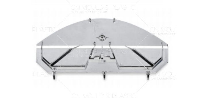
Mold designers shall meticulously carry out mold design in strict accordance with the abovementioned references and requirements provided by the client. During the design process, each requirement shall be translated into specific technical details and presented in the form of drawings or technical documentation. The design process generally follows the procedures below:
1.Analysis and Comprehension of Plastic Product Drawings and Physical Samples
Prior to mold design, a detailed analysis and comprehension of product drawings or physical samples are mandatory. The analysis covers the following aspects:
(1) Geometric configuration of the product;
(2) Dimensions, tolerances, and design benchmarks;
(3) Technical specifications (i.e., performance requirements);
(4) Plastic material name and grade;
(5) Surface finish requirements.
2.Determination of Injection Molding Machine Model
The selection of injection molding machine specifications is primarily based on the product's size and production volume. Designers shall consider the following parameters:
Injection capacity, clamping force, and model conversion rate;
(1) Effective mold mounting area (distance between tie bars);
(2) Mold thickness tolerance, ejection mechanism type, and stroke length.
If the client has specified a machine model, designers must verify its parameters. If requirements are unmet, consultation with the client for machine replacement is necessary.
3.Determination of Cavity Quantity and Arrangement
Cavity number is determined by factors including:
(1) Product weight vs. machine injection capacity;
(2) Projected area vs. clamping force;
(3) Mold dimensions vs. machine mounting space;
(4) Dimensional accuracy requirements;
(5) Color consistency;
(6) Presence of side cores and ejection methods;
(7) Production volume (monthly/annual batches);
(8) Economic efficiency (production cost per cycle).
These factors may conflict, requiring trade-offs to prioritize critical requirements.
After determining cavity numbers,their arrangement must optimize mold size, gating system balance, core pulling mechanisms, and thermal management. Adjustments are often needed to coordinate with parting surface and gate location decisions.
4.Determination of Parting Surface
The parting surface, sometimes predefined in foreign product drawings, is often determined by designers. Key principles include:
(1) Avoid impacting product aesthetics, especially for appearance-critical parts;
(2) Ensure dimensional accuracy;
(3) Facilitate mold manufacturing, particularly cavity machining;
(4) Optimize gating, venting, and cooling systems;
(5) Ensure reliable ejection, preferably leaving the product on the moving mold;
(6) Simplify metal insert installation.

5.Design of Lateral Parting and Core Pulling Mechanisms
Lateral mechanisms must be robust and avoid interference with ejection systems. If interference is unavoidable, a pre-ejection reset mechanism shall be incorporated.
6. Design of Gating System
The gating system design includes:
Main runner selection, runner cross-section geometry and dimensions, gate location, type, and cross-sectional size.
For point gates, a gate removal mechanism is required to ensure runner ejection. Gate location selection follows these principles:
(1) Position gates on the parting surface for easy cleaning;
(2) Minimize flow path length and ensure uniform fill;
(3) Direct melt flow toward thick-walled sections;
(4) Avoid direct impact on cores, inserts, or cavity walls to prevent deformation;
(5) Minimize weld lines or position them in non-critical areas;
(6) Promote parallel flow and efficient venting;
(7) Place gates in easily trimmable locations without compromising aesthetics.

 English
  français
  Deutsch
  Español
  italiano
  русский
  português
  العربية
  dansk
dansk  Suomi
Suomi  Svenska
  norsk
norsk 
