Hardness Test
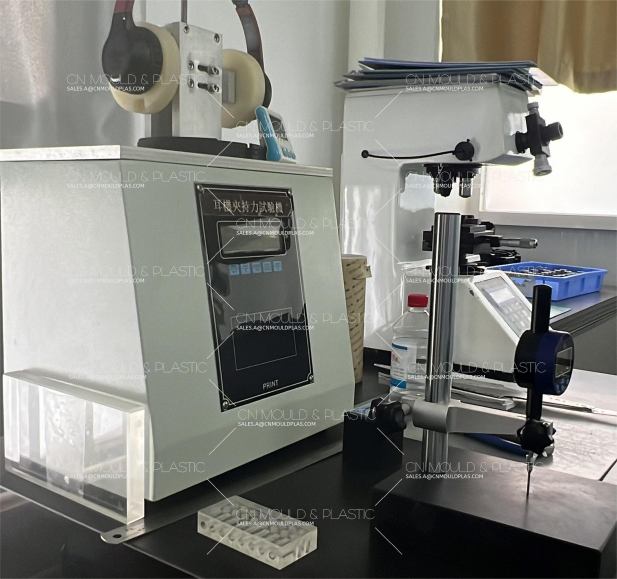
The hardness test is a simple method to predict the strength and wear - resistance of mold materials. Although there are various methods for determining hardness, they are basically divided into two categories: indentation hardness methods and rebound hardness methods.
Indentation hardness methods involve pressing an indenter into the test material and expressing the hardness by measuring the size of the indentation. Commonly used ones include the Brinell hardness test, Vickers hardness test, and Rockwell hardness test.

Compared with other indentation hardness tests, the Brinell hardness test (JIS Z 2243) has a relatively large indentation force and indentation size, making it suitable for determining the average hardness of the entire material. Therefore, it is often used to determine forged and rolled steels in tool and die steels. The indenter is made of cemented carbide, and recommended matching combinations can be selected for the test force, indenter diameter, and indentation diameter.
The indenter of the Vickers hardness test (JIS Z 2244) is a square - based pyramid diamond. Since the hardness remains constant even when the test force changes, it is not limited by the size, thickness of the specimen, or the size of the measurement area. The test can be carried out by changing the test force. For example, it can be used to measure the hardness distribution of the nitrided layer and carburized layer, where the hardness changes from the surface layer to the interior.
The Rockwell hardness test (JIS Z 2245) can measure a wide range of hardness values through the combination of three test forces and two indenters (conical diamond and hard ball). During the measurement, the diamond indenter or hard - ball indenter first applies an initial test force, then a full test force, and then returns to the initial test force. The hardness can be calculated from the difference in the indenter penetration depth.
The Shore hardness test (JIS Z 2246) is a test in which a stylus drops from a certain height to impact the test material, and the hardness of the material is characterized by the height of the stylus's elastic rebound. The test equipment is small, portable, and easy to operate, so it is convenient for measuring the hardness of large parts. In addition, since the indenter is small, it can also be used to measure heat - treated parts. However, the Shore hardness test is prone to human measurement errors and can only be used as a reference value. Moreover, as a rebound hardness test, it has the weakness of being easily affected by the surface shape and residual stress.
Tensile Test (JIS Z 2241)
The tensile test is a test in which an axial load is applied to a specimen and it is slowly stretched until fracture, from which values such as yield strength, tensile strength, elongation after fracture, and reduction of area are obtained. JIS stipulates various specimens. The load during stretching is measured by a load cell, and the elongation is measured by a scale. For tool and die steels, since there is no yield phenomenon, the load - elongation curve is used to find the stress corresponding to 0.2% residual plastic deformation, which is taken as the 0.2% yield stress. The calculation methods for various characteristic values are as follows:
Yield strength (MPa) = Yield load (N) / Original cross - sectional area of the specimen (mm²)
Tensile strength (MPa) = Maximum load (N) / Original cross - sectional area of the specimen (mm²)
Elongation after fracture A = (Gauge length after fracture - Original gauge length) / Original gauge length
Reduction of area Z = (Original cross - sectional area - Minimum cross - sectional area after fracture) / Original cross - sectional area
In addition, when tool and die steels are in the high - hardness range of over 50 HRC, special specimens can be used to prevent cracking originating from threaded holes.
Bending Test (JIS Z 2248)
The bending test specified in JIS Z 2248 is a method in which specimens with various cross - sectional shapes are bent to a specified angle within a specified bending radius in a certain test force direction, and then the bent part is inspected for cracks and other damages.
Fundamentally, the bending test specified in JIS Z 2248 is used to determine the strain energy of the material. However, the bending test for tool and die steels is to determine the bending strength (flexural strength) corresponding to the bending stress and the deflection amount at fracture, so different methods are used. Generally, for specimens with cylindrical or rectangular cross - sections, the three - point bending test method with two support points and one loading point is adopted.
Impact Test (JIS Z 2242)
The impact test is specified in JIS Z 2242 as the Charpy impact test method for metallic materials. The impact test is a test in which a specimen is broken by a testing machine, and the impact toughness is obtained by using the energy consumed. For tool and die steels, for materials with high toughness such as annealed materials and hot - working die steels, No. 3 specimen (U - notch) or No. 4 specimen (V - notch) is used. For high - hardness materials such as cold - working die steels and high - speed tool steels, which are not specified in JIS, specimens with a relatively gentle notch shape such as the C - notch specimen with 10R are generally used.
The size of each specimen is 10mm x 10mm x 55mm. These specimens are loaded onto a specimen holder with a 40mm interval and broken at one time by a pendulum from the back of the notch. After the pendulum drops, it will swing upward due to the reaction force. The potential energy difference between the initial upward swing amount and the upward swing amount after impact fracture is the energy absorbed by fracture.
The calculation method for impact toughness is as follows:
Impact toughness (J/cm²) = Impact absorbed energy (J) / Original cross - sectional area of the notch part (cm²)
In addition, there are also evaluation methods such as observing the fracture surface, measuring the ratio of brittle fracture surface area, and the width expansion amount (lateral expansion amount) of the specimen.
Furthermore, the impact test can be further carried out by changing the test temperature, and the relationship curves between the impact absorbed energy, the ratio of brittle fracture surface area, and the test temperature are plotted. Here, the test temperature at which the ratio of brittle fracture surface area reaches 50% is called the brittle transition temperature. The lower this transition temperature, the higher the toughness.

 English
  français
  Deutsch
  Español
  italiano
  русский
  português
  العربية
  dansk
dansk  Suomi
Suomi  Svenska
  norsk
norsk 


