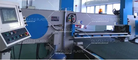
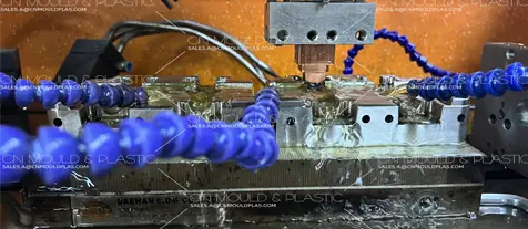
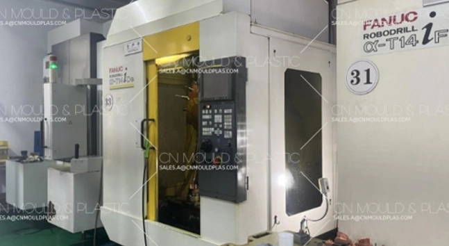
Characteristics of EDM
1.When using EDM to machine mold parts, the high current density from spark discharges generates enough heat to melt and vaporize any conductive material. So, it can handle all kinds of metals—hard, brittle, soft, sticky, or those with high melting points—including steel parts after heat treatment. This means that once parts are shaped by EDM, they won't be affected by post-heat-treatment deformation, which improves the machining accuracy of the mold.
2. Since EDM removes material not through mechanical cutting with tools, there's no mechanical force involved during processing, and no restrictions from such forces. That makes it perfect for drilling small holes, narrow slots, complex-shaped holes and cavities, as well as parts that are hard to machine with regular methods. It really simplifies the machining of mold components.
3. The electrical pulse parameters can be adjusted freely, so roughing, semi-finishing, finishing, and continuous machining can all be done on the same machine. This boosts work efficiency for China injection mold manufacturer.
4. EDM uses electricity directly, making it easy to achieve automatic control and automation in production.
5. Because EDM can shape cemented carbide parts, it creates convenient conditions for making carbide stamping dies, increasing their service life and durability.
6. EDM is easy to operate. The finished parts have high precision, with a surface roughness (Ra) reaching 1.25μm. So, after a little touch-up by fitters, the EDM-machined parts can be ready for assembly.
Process Scope of EDM
1.Piercing: Machining various shaped holes like die cavities, stripper plates, and fixing plates for cold stamping dies.
2. Cavity machining: Shaping cavities for compression molds, injection molds, die-casting molds, and forging dies.
3. Metal surface strengthening: For example, after EDM strengthening on the cutting edges of punches and dies, the mold's durability can be improved.
4. Grinding flat and cylindrical surfaces.
Process Flow of EDM Piercing
The process flow for EDM piercing of mold parts is as follows:
1. Choose the machining method
According to the drawing requirements, select the electrical machining process (direct fitting, indirect fitting, or secondary electrode method).
2. Select electrode material
Determine the electrode material based on the machining requirements, after deciding on the processing method and equipment.
3. Design the electrode
Design the electrode considering factors like gap, shape, effective edge length, and determine the cross-sectional shape, electrode length, and form.
4. Machine the electrode
Usually, form grinding or profile shaping is used.
5. Clamp the electrode
If the electrode is a segmented block or multiple electrodes are used to machine multiple shaped holes, clamp them together as per process requirements.
6. Prepare the workpiece
a. Prepare the part blank, with appropriate and uniform electrical machining allowance left at the piercing area.
b. Perform heat treatment as per process requirements to reach the required hardness.
c. Grind the upper and lower surfaces flat.
d. Remove rust and demagnetize.
e. Marking: Draw the contour lines of the shaped hole on the reverse side of the cutting edge.
7. Align the electrode
Clamp the electrode assembly on the spindle, and align the perpendicularity of the electrode with the worktable surface, as well as the parallelism between the electrode's side reference and the worktable's longitudinal and transverse axes.
8. Clamp and position the workpiece
Place the workpiece on the worktable, align its position relative to the electrode, and fix it.
9. Adjust the spindle head position
Move the spindle head so that the lower end of the electrode keeps a proper distance from the workpiece's upper surface.
10. Preparation for machining
a. Select the machining polarity and adjust the servo motor.
b. Maintain a certain liquid level height and adjust the oil suction force.
c. Adjust the machining depth indicator and select appropriate electrical parameters.
11. Start machining
a. Determine the feed rate and adjust the flushing pressure based on machining depth and stability.
b. During machining, check the depth, electrode wear, and machining status at any time; adjust immediately if problems are found.
12. Parameter conversion and intermediate inspection
a. After machining to a certain depth, switch the electrical parameters according to requirements for gap, edge height, slope, and electrode wear.
b. Check and adjust the machining depth at any time.
13. Inspect the part
After machining, carefully check if the part meets the drawing requirements.

 English
  français
  Deutsch
  Español
  italiano
  русский
  português
  العربية
  dansk
dansk  Suomi
Suomi  Svenska
  norsk
norsk 


