Strict process control is the key to producing products that are completely consistent, meet strict tolerances, and satisfy various quality standards. The troubleshooting guide described here mainly applies to the first stage, or the mold filling stage, which is characterized by speed control. Speed control means that the limits of hydraulic or plastic pressure allowed in the first stage are higher than those at the transition point from the first stage to the second stage. Time-based transition mode and hydraulic-based transition mode should not be used. If the product is both filled and packed during the first stage, it is advisable not to use the troubleshooting guide described here. The goal of the speed-controlled filling stage is to obtain a wide operating window so that by adjusting the machine (for the current injection), it can adapt to normal rate variations and produce good products. In the discussion, the first stage fills 99% of the entire product volume. At the end of this stage, the product is not completely filled, and may exhibit material shortage or sink marks. There is no significant pressure visible in the last area of filling, and if the pressure is stopped at the end of the first stage, the flow front may stop.
Troubleshooting Table
A troubleshooting table is provided here, which lists possible injection molding defects or processing defects. The troubleshooting table lists the possible causes of various defects and provides feasible solutions.
Causes and Solutions for Black Spots or Black Flakes on Products
Possible Causes | Feasible Solutions |
Poor screw or nozzle design | Pull and clean the screw and barrel. Check for carbon buildup behind the screw threads in the screw conveying zone and metering zone. Most general - purpose screws have this problem because there are dead zones behind the screw threads. General - purpose screws are not very suitable for injection molding of acrylic, polycarbonate, and SAN lenses. Special - designed dead - angle - free screws should be used to make the melt uniform. Check the check valve, nozzle tip cover, and nozzle tip to prevent sudden changes in the melt flow path. See "Screw Design". |
Nozzle is too long | Determine that the nozzle length is as short as possible, which is controlled by a PID temperature controller. |
Incorrect or poor hot runner design | Check the open or incorrect thermocouple values. Repair and replace those percentage - type thermocouples or autotransformers. Redesign the hot runner. Check the watt power density and heat source location. Check the position of the thermocouple. |
High melt temperature: hot zones in the screw or barrel | Use a thermal probe technique or an appropriate IR (infrared) sensor to check the melt temperature. IR sensors are generally not very accurate. Calibrate the temperature only when necessary. Check the hot zones of the screw and barrel. Are there any areas that exceed the set temperature? If so, adjust that area or the area before it. Reduce backpressure. Slow down the screw RPM. |
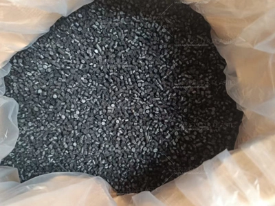
Impurities in the virgin resin | Use a whiteboard to check the virgin resin. Spread 1.5 kg of virgin resin over an area of 1500 cm² and examine it for 5 minutes under appropriate lighting. If there are black spots, note whether they are on the surface or inside the pellets, and inform the virgin resin supplier. |
Impurities in reprocessed or reground resin | Check the screw design, material grinding, and processing procedures. Discard or resell this batch of material. |
Excessive temperature or excessive residence time at melt temperature | Utilize 25% - 65% of the barrel capacity. In a space of less than 25%, the resin and additives are exposed to a long residence time, causing degradation. If possible, use a smaller barrel. Check whether the heating power is normal. The nozzle should be controlled by a PID controller. Check the high - shear dispersive mixing elements of the screw. Repair/replace. |
Excessively fine | Remove overly fine granules before processing; this is essential when making lenses. |
Special attention | If the black spot problem is caused by screw design, even the purest blend cannot solve the black spot issue. In 80% of cases, pulling and cleaning the screw is a wiser approach. The screw should be highly polished. |
Exhaust barrel | The exhaust ports of the exhaust barrel are usually poorly designed, with dead zones or material - hanging areas. Moreover, mechanical cleaning of this area is quite difficult, but it must be cleaned.
|
Reasons for the black stripes on the product and the solutions
Possible Causes | Feasible Solutions |
Sharp angles or corners at the gate | Polish the gate area, round off sharp corners, change the gate type, or expand the gate. |
Hot runner | Check for proper temperature control, burnt - out heating elements, and open thermocouples. Check the depth of the probe relative to the gate surface and calculate thermal expansion. Check for material - hanging areas or dead corners. |
Poor nozzle temperature control | The temperature of the nozzle is extremely difficult to control. If the nozzle length exceeds 3 in (75 mm), the thermocouple should be positioned at 1/3 of the nozzle length from the nozzle tip. For nozzles 3 in (75 mm) or shorter, it is better to embed the thermocouple within the hexagon on the nozzle body. For longer nozzle bodies, the thermocouple should be embedded below the heating band in a butterfly - shaped thermocouple. The nozzle should be controlled by a PID controller; percentage - type thermocouples or autotransformers should not be used. Do not fix the thermocouple to the heating band clip with screws. Clean the nozzle and check for obstructions. |
Sharp corners at the screw tip or broken check valve | Check the entire melt flow path for any adhering substances, sharp corners, grooves, etc. Check all plasticizing components: screw, screw tip, check ring, screw threads, etc. |
Impurities | Check for foreign material resins. |

 English
  français
  Deutsch
  Español
  italiano
  русский
  português
  العربية
  dansk
dansk  Suomi
Suomi  Svenska
  norsk
norsk 
