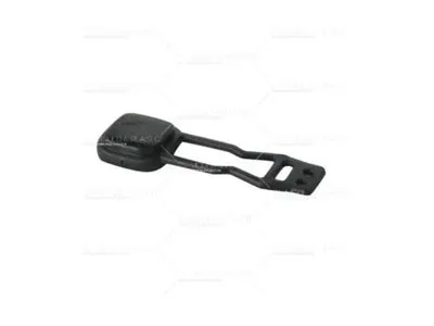
Long, strip-like, or thin-walled products are different from regular-shaped ones. They easily run into issues like warping or deformation because the runner is too long or narrow. This mainly comes from uneven shrinkage during plastic processing.
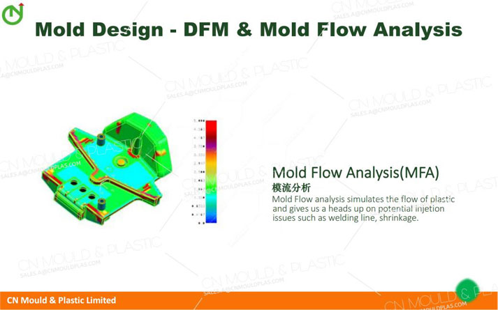
Molds for these products rarely work perfectly on the first test. Each test usually means adjusting gates, runners, etc. So, it’s smart to use runner analysis software (like Mold flow) during design—this helps cut down on mold repairs after manufacturing.

Complex-shaped products are hard to get consistent manufacturing processes for. During testing, we often use high pressure to fill and hold the mold, but that raises risks. For example, it puts stricter demands on how parts like the mold core fit together. You might get more flash or burrs, and in bad cases, small cores might even shift position. All this means lots of test runs and repairs are almost unavoidable.
From a test molding perspective, differences in product dimensional accuracy also affect mold making. Molds always have hard-to-machine spots, which can lower precision. Later, during testing, if the injection process is tweaked to meet other size requirements, problems pop up. Like, burrs might form where mold parts fit together. When demolding, these burrs can break, leaving that spot rough on every product afterward.
If a product’s design would mean tons of test runs, sometimes it’s better to split it into two parts that snap together instead of one. It’s a bit wasteful, but acceptable when time is tight.
A mold’s outer size has a big impact on testing. Follow these rules:
1. Molds used on the same injection machine should have roughly the same height (or at least not differ much). This saves time when setting up the mold.
2. No part of the mold should be bigger than the largest injection machine in your workshop can handle. This avoids having to outsource work.
3. If you add extra parts, their maximum size (including movement range) must not bump into the injection machine.
How rough a mold’s surface is affects both the product’s look and test molding. Making surfaces smoother usually takes time-consuming work like grinding.
A rough core surface can make demolding tough. In bad cases, the ejector pins might damage or pierce the product, leaving it stuck to the moving mold. This wastes time.
If the product is thin-walled or the plastic shrinks little, a rough cavity surface can make the product stick to the fixed mold. Worst case, you can’t get it out without taking the mold apart—this is time-consuming, tiring, and risks damaging the cavity.
The right roughness should let the product stick slightly to the moving mold but still come out easily, without ruining its look.
A mold is a device where melted plastic is poured into a custom-made cavity. Once it cools down, the plastic takes the exact shape of that cavity, forming the product.
Looking at how the plastic flows, a mold's structure includes runners and gates. When it comes to heat balance, molds have two main parts: heating and cooling systems.
The whole point of cooling or heating a mold is to get high production efficiency and top-quality products. For plastics with low melting points and good flow ability, cooling the mold can shorten the production cycle. But for some plastics that don't flow well, we need to heat the mold to make them more fluid. Since molds eventually need to cool down anyway, let's start by talking about cooling.
Except for some small product molds that can just cool naturally in the air to meet production needs, most molds need special cooling devices. If cooling is a big issue and you just need regular cooling, direct flow or direct circulation cooling devices are usually used (see Figure 1-1).
There are tables 1-1 and 1-2 for the mold temperatures commonly used in plastic injection molding. The plastics in Table 1-1 have low viscosity and good flow ability, so the mold temperature is controlled below 100°C. Thin-walled and small plastic parts can be cooled by the mold's own heat dissipation. For thick-walled and larger plastic parts, only 5% of the heat is dissipated into the atmosphere through radiation and convection, while 95% needs artificial cooling, usually through cold water cooling. The cooling principle is to keep the mold at the lowest possible temperature.
The plastics in Table 1-2 have high viscosity and poor flow ability, so the mold temperature is generally controlled above 100°C. The cooling principle here is to keep the mold at a temperature slightly lower than the thermal deformation temperature of the plastic.
Table 1-2 Plastics and Mold Temperatures (1)
Plastic | Mold Temperature/℃ |
PP (Polypropylene) | 50~90 |
PS (Polystyrene) | 30~60 |
ABS (Acrylonitrile-Butadiene-Styrene Copolymer) | 50~80 |
Table 1-3 Plastics and Mold Temperatures (2)
Plastic | Mold Temperature/℃ |
PC (Polycarbonate) | 90~120 |
PPS (Polysulfone) | 130~150 |
POM (Polyoxymethylene) | 90~120 |
From the heat formula, we know that the heat Q (kJ) transferred from the plastic to the mold is:
Q = 3600AKθt
In the formula:
· A ---- Heat transfer area (m²);
· K ---- Heat transfer coefficient of plastic to the cavity [kJ/(m²·h·℃)];
· θ ---- Average temperature difference between the cavity and the plastic (℃);
· t ---- Cooling time (s).
If we want to improve productivity, we should shorten the cooling time: either increase the temperature difference θ between the plastic part and the cavity, pass cold water through the high-temperature areas, and hot water through the low-temperature areas.
The key to test molding is to control the temperature difference of the cooling water.
Common mold heating methods include hot water, hot oil, hot air, or steam heating, etc. Just like water cooling, hot water, hot oil, and steam heating methods require opening channels for the heating medium in the mold. There are many heating devices for molds. Since electric heating controllers are mature, stable, accurate, and reliable, a large number of them are currently used to control mold temperatures. Common ones include electric heating plates, electric heating frames, electric heating coils, and electric heating rods. The selection of heaters generally has specific purposes, so when debugging such molds, it is best to communicate with the designers to understand the intention behind setting up the heaters and pay special attention during test molding to see if the design intentions can be achieved.
Electric heating is used to make certain control points reach the required temperature, so when the test molding reaches a stable state, it is necessary to check whether these points are controlled as required. Some heating is to increase the mold temperature over a large area. Since this kind of control itself is a vague target with no clear requirements but only general needs, a lot of tests are needed during test molding. Temperature control should be combined with the injection molding process to try to approach and achieve the design goals.

